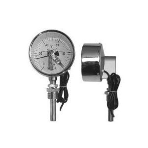
Rci460 Da Lt

Rotork

Teslimat Seçenekleri
Ücretsiz teslimat (Kapı Teslim)
Tedarik süreci min. 3-4 hafta
yurtiçi kargo

Rotork ürünlerini Türkiye genelinde kapı teslimi olarak satın almak istiyorsanız, lütfen talebinizle ilgili ürün kodları ve miktarı içeren bilgileri, iletişim bilgilerinizle birlikte info@yursat.com.tr adresimize gönderiniz. Ekibimiz en kısa sürede sizlere satış teklifi sunacaktır.
Rci460 Da Lt ve diğer modellerimizi içeren geniş ürün portföyümüzü görmek için aşağıdaki listeyi kontrol edebilirsiniz. Eğer ihtiyacınız olan ürünü bulamıyorsanız, lütfen bizimle iletişime geçmekten çekinmeyin, yeni talebinizi mail gönderebilir ya da Teklif İste formunu doldurabilirsiniz.

Firmamız, Rotork Türkiye Distribütörü veya temsilcisi değildir. Firmamız sipariş durumunda, belirtilen ürünlerde sadece Orjinal ve yeni ürün teklifi sunmaktadır. Bu sitede gösterilen Özel marka adları ve ticari markalar ilgili sahiplerinin mülkiyetindedir.
􀁸 Spindle turn run button
􀁸 Spindle turn stop button
􀁸 Local / remote selector switch
 Emergency stop (Protected)

f) The condition of the circuit at the cable terminals to be connected to the exhaust control panel from the field
there will be LEDs showing.
g) All conditions required for PLC panel are also valid for this panel.
Actuators:
a) Exhaust regulation and input actuators will be renewed. 1 input bypass in each exhaust and
There is one regulation actuator.
b) Engineering studies, measurements, mechanical, electrical
and, if necessary, construction works, commissioning and adjustments will be made within the scope of the CONTRACTOR.
c) Regulation actuators are spindle and the adapter will be connected to the shaft with flange.
d) Input actuators are arm type and all necessary fittings for these actuators,
mechanisms will be provided and commissioned by adjusting them.
e) Actuators must be in IP 68, ATEX EExd IIC T4 protection class.
f) Actuator working voltage will be 3 Phase, 400 V ± 10V, 50 Hz. Min. S2 - (15%) with engine type
should be. Insulation class: F.
g) Clamps with actuators shall be proportionally controlled. The opening ratio is proportional to PLC
It should be moved.
h) Input – Output will work remotely via PLC and SCADA with 4-20 mA signal.
i) Actuators, with IP65 protection class limit switch box group, flap mounted and
will be shipped calibrated.
j) There will be 1 thermal overload switch in the actuators.
k) The actuator shall have a coupled local control unit. Also separate for controlling actuators
a local control panel will be provided and installed.
l) Actuators can be adjusted open and closed with limit switch for open and closed position information
will have a torque limit switch. Proximity sensor will be used as limit switch.
m) It should be a digital position indicator.
n) Time from full closed to full open should not exceed 60 seconds. Also input / output difference
It will not exceed 2%.
o) A suitable diameter handwheel should be available on the actuator for manual operation. actuators
It will be ISO9001, CE Certified.
p) Actuators will be electronic starters (thyristor triggered).
q) It should be Bluetooth Controlled and the information and settings of the actuator can be done via this remote.
It should be done.
r) Terminal boxes must have a double O-ring sealing system.
s) Liquid oil should be used to distribute heat evenly inside the actuator gearbox, grease
oil should not be used.
t) The actuator body must be of aluminum or higher quality material.
u) There should be a double gear clutch mechanism that provides motor and manual control, motor or
opening / closing with the handwheel when a malfunction occurs in the gearbox connected to the engine
able to provide
v) Data tracking and recording (vibration, torque, etc.) should be made on the actuator,
The information should be visible on the LCD screen or transferred to the computer.
w) Necessary precautions to prevent valve's position information to be lost in case of power failure
and take the valve position until the power comes back on the actuator LCD screen.
It should be ensured to be read without interruption.
x) Condensation formation against resistance defects that may occur in the actuator.
To prevent it, the manufacturer must take precautions without using resistance.
y) The actuator should be able to detect vibration / vibration values ​​between 10Hz and 1kHz,
should be able to take and is resistant to vibration in this range and should not be damaged.
z) Actuators will be one of Schiebel, Auma or Rotork brands.
Instrumentation:
a) Actual values ​​of instruments such as temperature, pressure and level in the system
Analog inputs or A / D converters will be used in the control circuit to be able to read.
b) Instrumentation and PLC system; equipment for the operation of the exhaust
all interlocking required for normal operation and protection
It will have a structure to provide
c) Transmitters will be as uniform as possible (Connection types will be the same,
Half a finger like teeth). It will output 4-20 mA DC output signal in the 0-100% measurement range.
d) Protection classes of all instruments to be supplied shall be minimum IP 65.
e) The pressure gauge panel in each exhaust unit will be renewed. Above the locker
oily manometers (electronic pressure sensor with analog indicator) and parallel to these
pressure transmitters (digital manometers) to be connected as ex-proof
will be assembled with its panel. The project of the manometer panel is in ANNEX-3
It is given. Measurements taken from pressure transmitters to PLC via RIO / control panel
It will be transferred. The software related to this system is made in PLC and necessary information and alarms are given to SCADA.
will be transferred. The guards at SCADA will be under operator control.
f) The level of hydraulic oil tanks will be measured with a pressure type sensor.
g) The label tags of the estrus will be chrome. Before being supplied for these labels
compatibility with the sample should be taken.
h) Vibration sensors to be supplied for motor and fan vibrations are ex-proof, 4-20 mA output
and it will be provided in the working range of 0-25 mm / sec. ATEX and the sensors to be supplied
IECX Group I and Group II certified certificates will be requested.
Regulation Actuators

􀁸 Spindle turn run button 􀁸 Spindle turn stop button 􀁸 Local / remote selector switch Emergency stop (Protected) f) The condition of the circuit at the cable terminals to be connected to the exhaust control panel from the field there will be LEDs showing. g) All conditions required for PLC panel are also valid for this panel. Actuators: a) Exhaust regulation and input actuators will be renewed. 1 input bypass in each exhaust and There is one regulation actuator. b) Engineering studies, measurements, mechanical, electrical and, if necessary, construction works, commissioning and adjustments will be made within the scope of the CONTRACTOR. c) Regulation actuators are spindle and the adapter will be connected to the shaft with flange. d) Input actuators are arm type and all necessary fittings for these actuators, mechanisms will be provided and commissioned by adjusting them. e) Actuators must be in IP 68, ATEX EExd IIC T4 protection class. f) Actuator working voltage will be 3 Phase, 400 V ± 10V, 50 Hz. Min. S2 - (15%) with engine type should be. Insulation class: F. g) Clamps with actuators shall be proportionally controlled. The opening ratio is proportional to PLC It should be moved. h) Input – Output will work remotely via PLC and SCADA with 4-20 mA signal. i) Actuators, with IP65 protection class limit switch box group, flap mounted and will be shipped calibrated. j) There will be 1 thermal overload switch in the actuators. k) The actuator shall have a coupled local control unit. Also separate for controlling actuators a local control panel will be provided and installed. l) Actuators can be adjusted open and closed with limit switch for open and closed position information will have a torque limit switch. Proximity sensor will be used as limit switch. m) It should be a digital position indicator. n) Time from full closed to full open should not exceed 60 seconds. Also input / output difference It will not exceed 2%. o) A suitable diameter handwheel should be available on the actuator for manual operation. actuators It will be ISO9001, CE Certified. p) Actuators will be electronic starters (thyristor triggered). q) It should be Bluetooth Controlled and the information and settings of the actuator can be done via this remote. It should be done. r) Terminal boxes must have a double O-ring sealing system. s) Liquid oil should be used to distribute heat evenly inside the actuator gearbox, grease oil should not be used. t) The actuator body must be of aluminum or higher quality material. u) There should be a double gear clutch mechanism that provides motor and manual control, motor or opening / closing with the handwheel when a malfunction occurs in the gearbox connected to the engine able to provide v) Data tracking and recording (vibration, torque, etc.) should be made on the actuator, The information should be visible on the LCD screen or transferred to the computer. w) Necessary precautions to prevent valve's position information to be lost in case of power failure and take the valve position until the power comes back on the actuator LCD screen. It should be ensured to be read without interruption. x) Condensation formation against resistance defects that may occur in the actuator. To prevent it, the manufacturer must take precautions without using resistance. y) The actuator should be able to detect vibration / vibration values ​​between 10Hz and 1kHz, should be able to take and is resistant to vibration in this range and should not be damaged. z) Actuators will be one of Schiebel, Auma or Rotork brands. Instrumentation: a) Actual values ​​of instruments such as temperature, pressure and level in the system Analog inputs or A / D converters will be used in the control circuit to be able to read. b) Instrumentation and PLC system; equipment for the operation of the exhaust all interlocking required for normal operation and protection It will have a structure to provide c) Transmitters will be as uniform as possible (Connection types will be the same, Half a finger like teeth). It will output 4-20 mA DC output signal in the 0-100% measurement range. d) Protection classes of all instruments to be supplied shall be minimum IP 65. e) The pressure gauge panel in each exhaust unit will be renewed. Above the locker oily manometers (electronic pressure sensor with analog indicator) and parallel to these pressure transmitters (digital manometers) to be connected as ex-proof will be assembled with its panel. The project of the manometer panel is in ANNEX-3 It is given. Measurements taken from pressure transmitters to PLC via RIO / control panel It will be transferred. The software related to this system is made in PLC and necessary information and alarms are given to SCADA. will be transferred. The guards at SCADA will be under operator control. f) The level of hydraulic oil tanks will be measured with a pressure type sensor. g) The label tags of the estrus will be chrome. Before being supplied for these labels compatibility with the sample should be taken. h) Vibration sensors to be supplied for motor and fan vibrations are ex-proof, 4-20 mA output and it will be provided in the working range of 0-25 mm / sec. ATEX and the sensors to be supplied IECX Group I and Group II certified certificates will be requested.
􀁸 Spindle turn run button
􀁸 Spindle turn stop button
􀁸 Local / remote selector switch
 Emergency stop (Protected)

f) The condition of the circuit at the cable terminals to be connected to the exhaust control panel from the field
there will be LEDs showing.
g) All conditions required for PLC panel are also valid for this panel.
Actuators:
a) Exhaust regulation and input actuators will be renewed. 1 input bypass in each exhaust and
There is one regulation actuator.
b) Engineering studies, measurements, mechanical, electrical
and, if necessary, construction works, commissioning and adjustments will be made within the scope of the CONTRACTOR.
c) Regulation actuators are spindle and the adapter will be connected to the shaft with flange.
d) Input actuators are arm type and all necessary fittings for these actuators,
mechanisms will be provided and commissioned by adjusting them.
e) Actuators must be in IP 68, ATEX EExd IIC T4 protection class.
f) Actuator working voltage will be 3 Phase, 400 V ± 10V, 50 Hz. Min. S2 - (15%) with engine type
should be. Insulation class: F.
g) Clamps with actuators shall be proportionally controlled. The opening ratio is proportional to PLC
It should be moved.
h) Input – Output will work remotely via PLC and SCADA with 4-20 mA signal.
i) Actuators, with IP65 protection class limit switch box group, flap mounted and
will be shipped calibrated.
j) There will be 1 thermal overload switch in the actuators.
k) The actuator shall have a coupled local control unit. Also separate for controlling actuators
a local control panel will be provided and installed.
l) Actuators can be adjusted open and closed with limit switch for open and closed position information
will have a torque limit switch. Proximity sensor will be used as limit switch.
m) It should be a digital position indicator.
n) Time from full closed to full open should not exceed 60 seconds. Also input / output difference
It will not exceed 2%.
o) A suitable diameter handwheel should be available on the actuator for manual operation. actuators
It will be ISO9001, CE Certified.
p) Actuators will be electronic starters (thyristor triggered).
q) It should be Bluetooth Controlled and the information and settings of the actuator can be done via this remote.
It should be done.
r) Terminal boxes must have a double O-ring sealing system.
s) Liquid oil should be used to distribute heat evenly inside the actuator gearbox, grease
oil should not be used.
t) The actuator body must be of aluminum or higher quality material.
u) There should be a double gear clutch mechanism that provides motor and manual control, motor or
opening / closing with the handwheel when a malfunction occurs in the gearbox connected to the engine
able to provide
v) Data tracking and recording (vibration, torque, etc.) should be made on the actuator,
The information should be visible on the LCD screen or transferred to the computer.
w) Necessary precautions to prevent valve's position information to be lost in case of power failure
and take the valve position until the power comes back on the actuator LCD screen.
It should be ensured to be read without interruption.
x) Condensation formation against resistance defects that may occur in the actuator.
To prevent it, the manufacturer must take precautions without using resistance.
y) The actuator should be able to detect vibration / vibration values ​​between 10Hz and 1kHz,
should be able to take and is resistant to vibration in this range and should not be damaged.
z) Actuators will be one of Schiebel, Auma or Rotork brands.
Instrumentation:
a) Actual values ​​of instruments such as temperature, pressure and level in the system
Analog inputs or A / D converters will be used in the control circuit to be able to read.
b) Instrumentation and PLC system; equipment for the operation of the exhaust
all interlocking required for normal operation and protection
It will have a structure to provide
c) Transmitters will be as uniform as possible (Connection types will be the same,
Half a finger like teeth). It will output 4-20 mA DC output signal in the 0-100% measurement range.
d) Protection classes of all instruments to be supplied shall be minimum IP 65.
e) The pressure gauge panel in each exhaust unit will be renewed. Above the locker
oily manometers (electronic pressure sensor with analog indicator) and parallel to these
pressure transmitters (digital manometers) to be connected as ex-proof
will be assembled with its panel. The project of the manometer panel is in ANNEX-3
It is given. Measurements taken from pressure transmitters to PLC via RIO / control panel
It will be transferred. The software related to this system is made in PLC and necessary information and alarms are given to SCADA.
will be transferred. The guards at SCADA will be under operator control.
f) The level of hydraulic oil tanks will be measured with a pressure type sensor.
g) The label tags of the estrus will be chrome. Before being supplied for these labels
compatibility with the sample should be taken.
h) Vibration sensors to be supplied for motor and fan vibrations are ex-proof, 4-20 mA output
and it will be provided in the working range of 0-25 mm / sec. ATEX and the sensors to be supplied
IECX Group I and Group II certified certificates will be requested.
By-Pass Actuators

􀁸 Spindle turn run button 􀁸 Spindle turn stop button 􀁸 Local / remote selector switch Emergency stop (Protected) f) The condition of the circuit at the cable terminals to be connected to the exhaust control panel from the field there will be LEDs showing. g) All conditions required for PLC panel are also valid for this panel. Actuators: a) Exhaust regulation and input actuators will be renewed. 1 input bypass in each exhaust and There is one regulation actuator. b) Engineering studies, measurements, mechanical, electrical and, if necessary, construction works, commissioning and adjustments will be made within the scope of the CONTRACTOR. c) Regulation actuators are spindle and the adapter will be connected to the shaft with flange. d) Input actuators are arm type and all necessary fittings for these actuators, mechanisms will be provided and commissioned by adjusting them. e) Actuators must be in IP 68, ATEX EExd IIC T4 protection class. f) Actuator working voltage will be 3 Phase, 400 V ± 10V, 50 Hz. Min. S2 - (15%) with engine type should be. Insulation class: F. g) Clamps with actuators shall be proportionally controlled. The opening ratio is proportional to PLC It should be moved. h) Input – Output will work remotely via PLC and SCADA with 4-20 mA signal. i) Actuators, with IP65 protection class limit switch box group, flap mounted and will be shipped calibrated. j) There will be 1 thermal overload switch in the actuators. k) The actuator shall have a coupled local control unit. Also separate for controlling actuators a local control panel will be provided and installed. l) Actuators can be adjusted open and closed with limit switch for open and closed position information will have a torque limit switch. Proximity sensor will be used as limit switch. m) It should be a digital position indicator. n) Time from full closed to full open should not exceed 60 seconds. Also input / output difference It will not exceed 2%. o) A suitable diameter handwheel should be available on the actuator for manual operation. actuators It will be ISO9001, CE Certified. p) Actuators will be electronic starters (thyristor triggered). q) It should be Bluetooth Controlled and the information and settings of the actuator can be done via this remote. It should be done. r) Terminal boxes must have a double O-ring sealing system. s) Liquid oil should be used to distribute heat evenly inside the actuator gearbox, grease oil should not be used. t) The actuator body must be of aluminum or higher quality material. u) There should be a double gear clutch mechanism that provides motor and manual control, motor or opening / closing with the handwheel when a malfunction occurs in the gearbox connected to the engine able to provide v) Data tracking and recording (vibration, torque, etc.) should be made on the actuator, The information should be visible on the LCD screen or transferred to the computer. w) Necessary precautions to prevent valve's position information to be lost in case of power failure and take the valve position until the power comes back on the actuator LCD screen. It should be ensured to be read without interruption. x) Condensation formation against resistance defects that may occur in the actuator. To prevent it, the manufacturer must take precautions without using resistance. y) The actuator should be able to detect vibration / vibration values ​​between 10Hz and 1kHz, should be able to take and is resistant to vibration in this range and should not be damaged. z) Actuators will be one of Schiebel, Auma or Rotork brands. Instrumentation: a) Actual values ​​of instruments such as temperature, pressure and level in the system Analog inputs or A / D converters will be used in the control circuit to be able to read. b) Instrumentation and PLC system; equipment for the operation of the exhaust all interlocking required for normal operation and protection It will have a structure to provide c) Transmitters will be as uniform as possible (Connection types will be the same, Half a finger like teeth). It will output 4-20 mA DC output signal in the 0-100% measurement range. d) Protection classes of all instruments to be supplied shall be minimum IP 65. e) The pressure gauge panel in each exhaust unit will be renewed. Above the locker oily manometers (electronic pressure sensor with analog indicator) and parallel to these pressure transmitters (digital manometers) to be connected as ex-proof will be assembled with its panel. The project of the manometer panel is in ANNEX-3 It is given. Measurements taken from pressure transmitters to PLC via RIO / control panel It will be transferred. The software related to this system is made in PLC and necessary information and alarms are given to SCADA. will be transferred. The guards at SCADA will be under operator control. f) The level of hydraulic oil tanks will be measured with a pressure type sensor. g) The label tags of the estrus will be chrome. Before being supplied for these labels compatibility with the sample should be taken. h) Vibration sensors to be supplied for motor and fan vibrations are ex-proof, 4-20 mA output and it will be provided in the working range of 0-25 mm / sec. ATEX and the sensors to be supplied IECX Group I and Group II certified certificates will be requested.

TEKLİF ALIN

fiyat teklifinizi en kısa sürede size sunmaktayız

Alanı Doldurunuz
İyi görünüyor!
Lütfen E-Postanızı Doğru Giriniz
İyi görünüyor!
Alanı Doldurunuz
İyi görünüyor!
Alanı Doldurunuz